Setting up the Bell MTS wireless Set-top box VIP 2502
This service is only available to MTS customers in Manitoba. To find support for your region, please select your province.
Instructions for Setting up the Installing a Bell MTS 4K PVR with a Bell MTS Giga Hub can be found here
The following steps will prepare you for the installation of your new wireless set-top box VIP 2502:
-
Connect the HDMI cable or component cables to your new wireless set-top box VIP 2502 and TV.
- If you are replacing an old set-top box, connect the cables from the old set-top box to the corresponding connections on your wireless set-top box VIP 2502.
- Wireless set-top boxes do not require a coaxial or Ethernet cable.
- If you have a USB device for your RF remote, ensure to plug it in to the your new wireless set-top box VIP 2502
-
Plug in your power adapter into your new wirless set-top box VIP 2502 and
connect the power adapter to a power outlet.
- Only use the power adapter that came with your new wireless set-up box VIP 2502.
- The lights on the front of the set-top box will flash briefly then go out for around one to two minutes.
Once you have completed the initial steps follow the steps corresponding to your internet hardware situation:
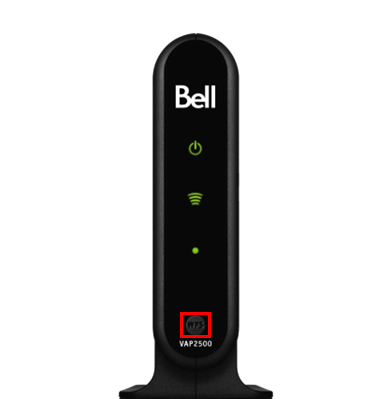
VAP2500 exists in home (no Home Hub 3000/Giga Hub)
- Turn on your TV and wait for the Connect prompt to appear on the TV. Do not press OK at this point. If you don't see the "Connect" prompt appear on the TV, ensure you TV, ensure your TV is set to the correct input (e.g. HDMI 1/HDMI 2/Video 1, etc.).
-
Press and hold the WPS button on VAP2500 for two seconds or
until WPS LED flashes green. WPS LED will flash green for two minutes.
Images may not be exactly as shown. - Within two minutes, go back to your set-top box and press OK on the front of your wireless set-top box VIP 2502.
- The set-top box will connect to the VAP2500 and restart. You will see a Fibe TV logo on your TV and a green Wi-Fi signal light on your set-top box when it is ready for use. Press SELECT or OK to watch TV.
For Home Hub 3000
- Turn on your TV and wait for the Connect prompt to appear on the TV. Do not press OK at this point. If you don't see the "Connect" prompt appear on the TV, ensure you TV, ensure your TV is set to the correct input (e.g. HDMI 1/HDMI 2/Video 1, etc.).
-
Press and hold the WPS button on the Home Hub 3000 to say
Hold to Connect TV receiver on the OLED screen, continue to
hold the button, a five minute timer will appear and the OLED will say TV
Receiver.

Images may not be exactly as shown. - Within the alloted time, go back to your new wireless set-top box VIP 2502 and press OK.
- The set-top box will connect to the HomeHub 3000 and restart. You will see a Fibe TV logo on your TV, and a green Wi-Fi signal light on your set-top box when it is ready for use. Press SELECT or OK to watch TV.
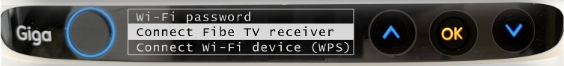
For Giga Hub
- Turn on your TV and wait for the Connect prompt to appear on the TV. Do not press OK at this point. If you don't see the "Connect" prompt appear on the TV, ensure you TV, ensure your TV is set to the correct input (e.g. HDMI 1/HDMI 2/Video 1, etc.).
-
Press the OK button on the Giga Hub. Use the
down arrow button until
Connect Fibe TV receiver is highlighted on the LED screen.
Images may not be exactly as shown. -
Press the OK button on the Giga Hub. A five minute timer
will appear
Note:
Pressing the OK button again will cancel the pairing process.
- Within the alloted time, go back to your new wireless set-top box VIP 2502 and press OK.
- The set-top box will connect to the Giga Hub and restart. You will see a Fibe TV logo on your TV, and a green Wi-Fi signal light on your set-top box when it is ready for use. Press SELECT or OK to watch TV.
General steps to maintain your Bell MTS Set-Top Box
Arris VIP2502 reference guide (PDF 801KB)
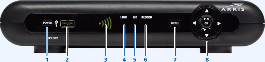
Front Panel Lights/Function
| Key | Item | Function |
|---|---|---|
| 1 | POWER Switch |
Press quickly to turn the set-top box on or off. Press and hold for 10 seconds to perform a full restart. |
| 2 | USB | USB 2.0 port (Not compatible with Bell MTS service). |
| 3 | SIGNAL | Indicates signal quality. |
| 4 | LINK | Green: Connected to the Bell MTS TV network. |
| 5 | HD | Blue: Set-top box is receiving an HD signal. |
| 6 | RECORD | Red: PVR is recording one or more shows. |
| 7 | MENU | Displays the on-screen menu. |
| 8 | UP/DOWN/LEFT/RIGHT/OK |
Arrows allow you to navigate the menu. OK selects/accepts channel and menu options. |
Rear Panel Function
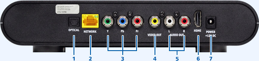
| Key | Item | Function |
|---|---|---|
| 1 | OPTICAL | S/PDIF output. High-quality digital audio output (to a digital home theatre receiver). |
| 2 | NETWORK | Ethernet 10/100 Base-T RJ-45 port. |
| 3 | Y PB PR | RCA-type component video outputs to an HD-TV or home theatre receiver. It carries video only; you must also connect to the TV or home theatre receiver for audio. |
| 4 | VIDEO OUT | RCA-type, standard-quality video output (to a TV, VCR, DVD recorder, or other device). It carries video only, you must also connect to the TV or home theatre receiver for audio. |
| 5 | AUDIO OUT L & R | Stereo audio outputs (Left and right RCA-type). |
| 6 | HDMI | High-Definition output. Connects to an HD-TV or home theatre receiver with an HDMI input. |
| 7 | POWER | DC power adapter connector. |
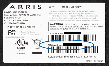
Finding the MAC Address
You can find the MAC address on a sticker on the bottom of the unit.